Truck Camper Solar Project
Part 1 – Adding panels to roof
MinniesMommy.com
We spent 6 weeks in Arizona this past winter and our solar and battery system couldn’t keep up while we were boondocking. We aren’t sure what the wattage of the original panel was supposed to be and we had two lead-acid batteries that we promptly screwed up because the refrigerator switched itself to 12v while on automatic and drained the batteries. We no longer let the refrigerator choose on its own, and switch from AC to LPG manually. This might be a problem when we get an inverter installed, as the fridge will think it has AC power and won’t beep at us when we unplug. I’m still thinking about what to do with that. I don’t really want to redo all of the AC wiring and isolate just the refrigerator. I want to still be able to possibly use the microwave and even the air conditioner on the batteries.
Anyway, we made the decision that we need to upgrade our ability to charge and store power, and need bigger “tanks” and a little more “gas” to fill those tanks in the fall and winter when the sun is spending more time in the southern hemisphere.
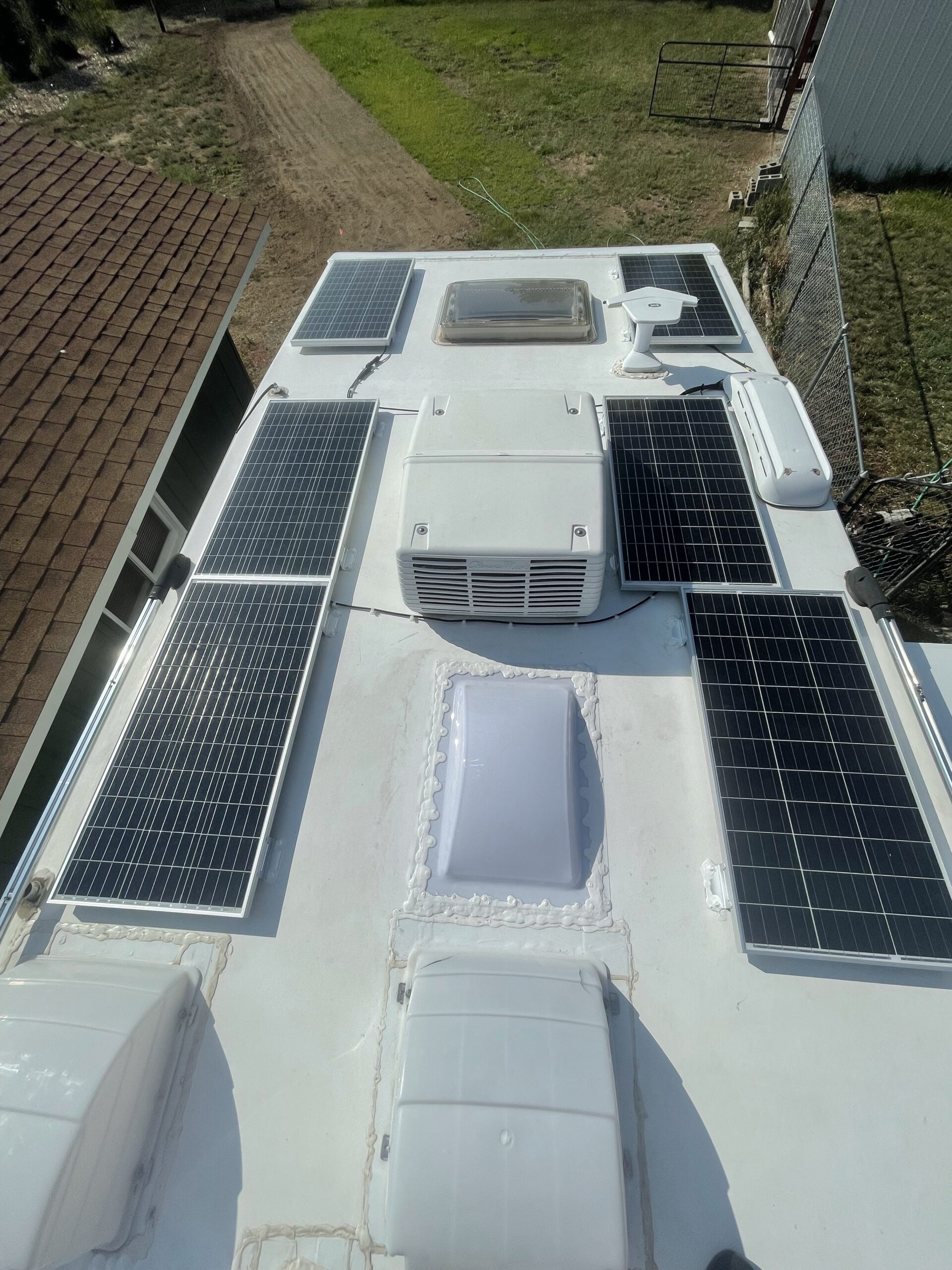
After a ton of research, I decided on 6 100W HQST solar panels to provide the “gas”. These were the most compact and lightest monocrystalline panels that I could find. Real estate on a camper is pretty limited, especially with three skylights, two vents, an air conditioner, antennas and plumbing vents. You can purchase them directly from HQST or from Amazon here: HQST Solar Panel. I also ordered 10 pairs of MC4 connectors, 1 pair of Branch Connectors and 6 sets of Solar Panel Mounting Z Brackets.
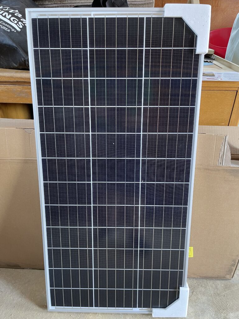
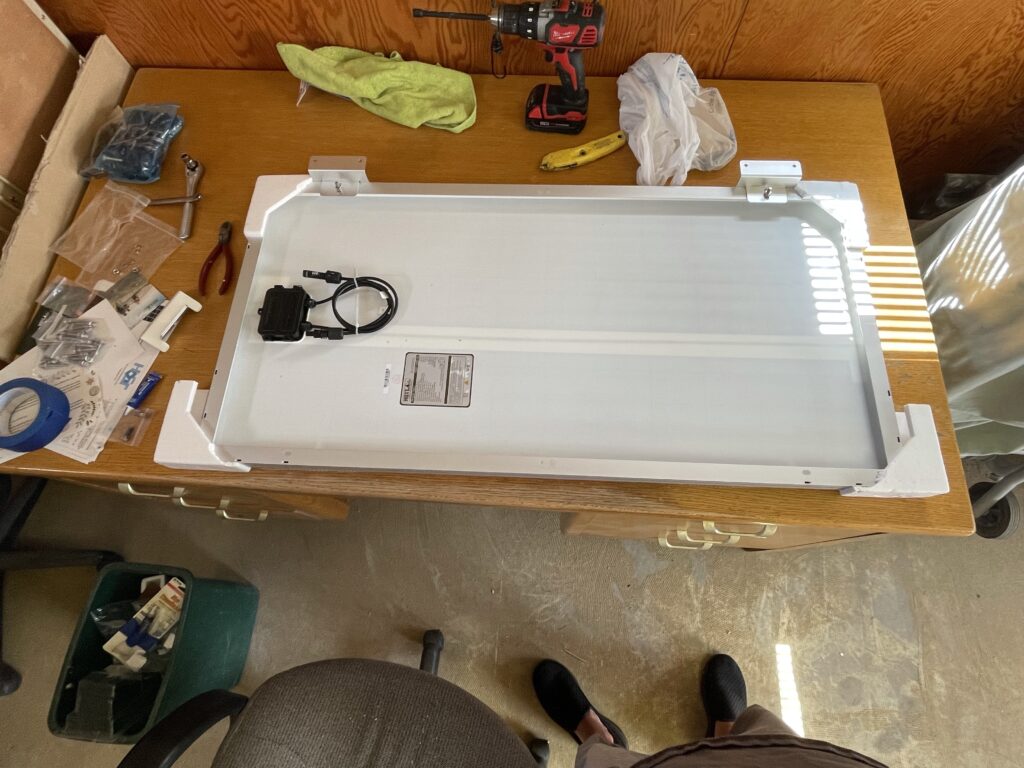
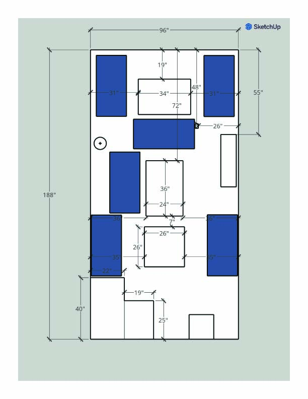
I tried making a SketchUp file before ordering the panels to make sure I could fit 6 of them up there. I measured everything and put every obstruction that was on the roof and then played with the solar panels. I could probably add two more but I think that’d be overkill for the number of batteries that I can find space for. And weight is still a consideration. I did end up changing the layout a bit. Lining them up worked better for the series connections, as the cables just barely reached one another. Shading is a concern, especially since the air conditioning unit is so tall, and will definitely reduce the solar output. I will update after we’ve had a chance to use this system for winter camping.
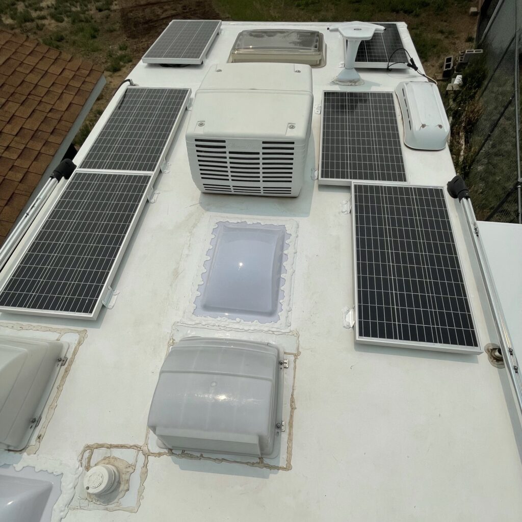
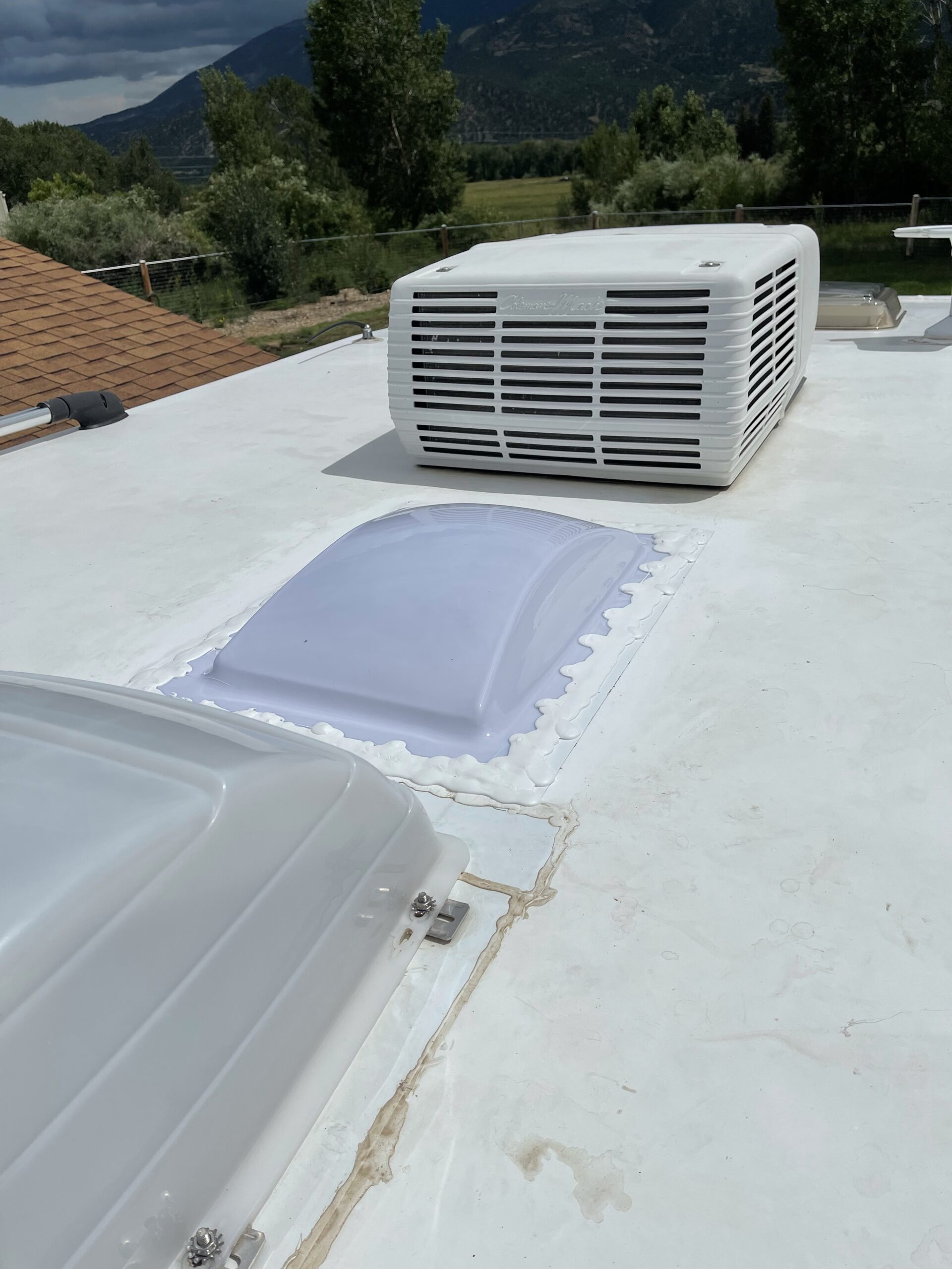
This is how it actually laid out. I used screws, adhesive and lap sealant to attach the panels. I had nightmares for several nights but I have given them several yanks and they seem to be as stable as everything else up there. Time will tell.
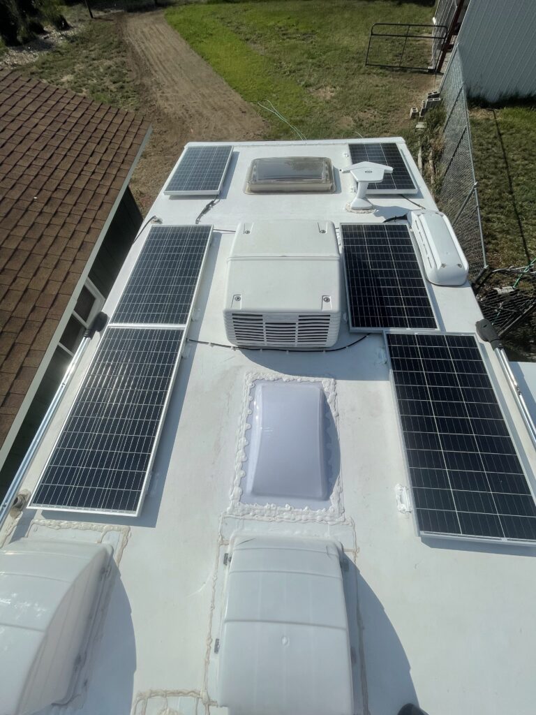
I needed some extra extension wires as these are wired in series-parallel. The three panels on the left are wired in series and the three on the right are wired in series and then they are combined in parallel. As I understand it, this essentially combines the voltage on each set of three and then combines the current on the two sets. If I combined all six panels in parallel, I’d likely have to have larger wiring and a lot more fuses. If this setup doesn’t work well, I suppose I can change it.
Here is how the panels turned out wired together. After the first order of clips turned out to be way too small, I found some others that I think will work. If they pop off, I guess I’ll glob some lap sealant on them. 😂
You can get these clips on Amazon here: Viaky 30 Pieces White Adjustable Cable Clips
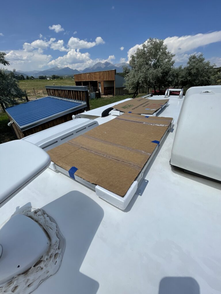
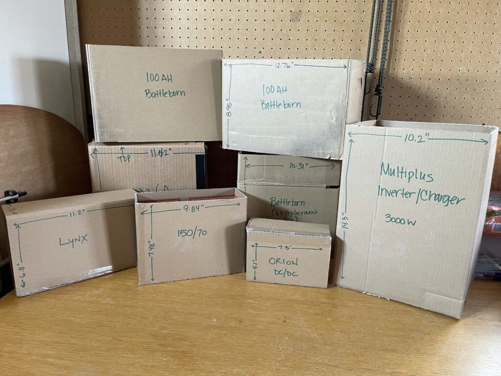
I made a bunch of cardboard boxes so I could visualize the components that I might be adding. There are a lot of different products out there, especially batteries. Check back to see which products I chose and why.
Then I took the lead-acid batteries out of the step and started trying to make sense of what is there and how the Tetris game is going to work out. While I had everything out, I cleaned out the battery boxes and vacuumed up the debris. This is how it looked after removing the batteries and BEFORE I cleaned up. I always try to take pictures of the “before” so that I can remember how it looked if something accidentally gets unplugged.
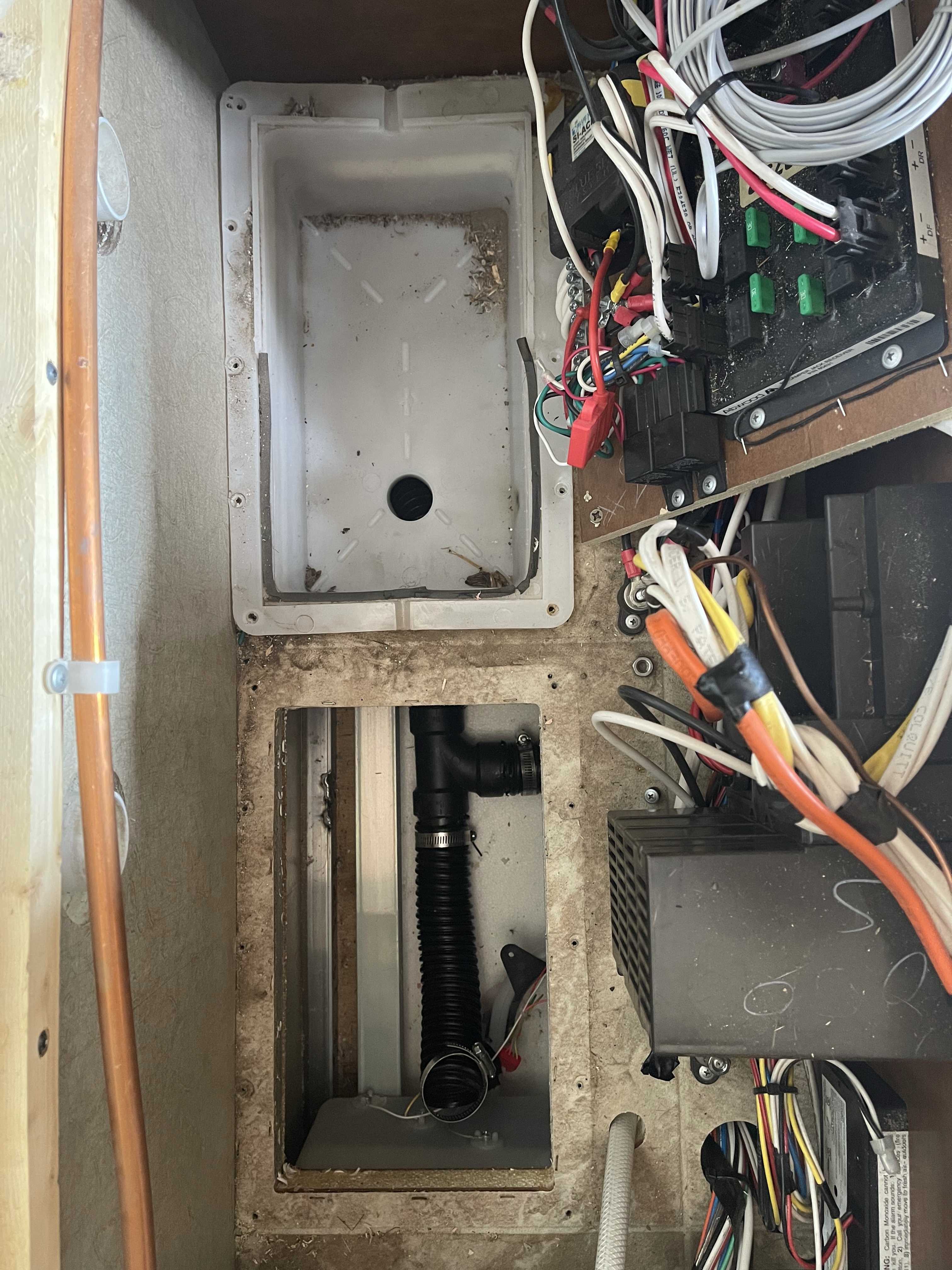
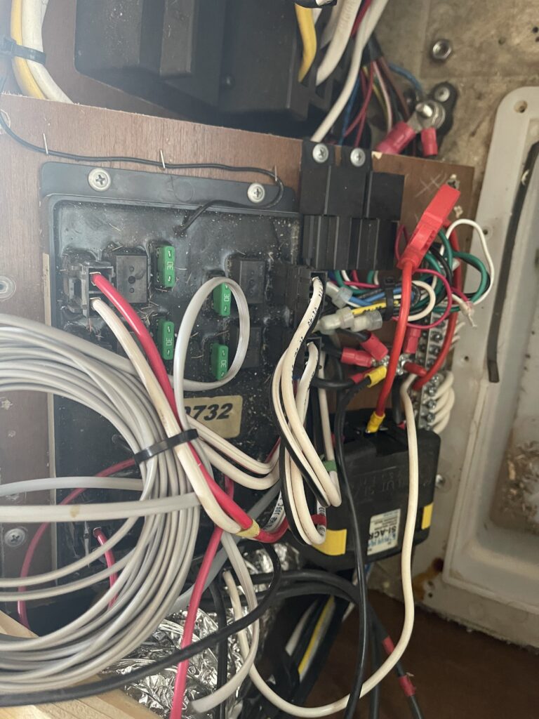
There is access to the fresh water tank and sensors from the battery box that is removed in this picture. The tangled mess of wires are attached to the jacks and slideout circuit board and various other components. That is probably going to be one of the most difficult things to work around. We shall see!
I poked around and the space between the two batteries doesn’t seem to have any framing. This is good, because we will likely have to enlarge the holes a bit so we can drop larger lithium batteries in place. Follow along, as this area will be changing soon!
Some links may be affiliate links. I may earn from qualifying purchases at no additional cost to you.
Minnie’s Mommy is a participant in the Amazon Services LLC Associates Program, an affiliate advertising program designed to provide a means for sites to earn advertising fees by advertising and linking to Amazon.com.
Minnie’s Mommy is a participant in the Wal-Mart.com USA, LLC Affiliate Marketing Program, an affiliate advertising program designed to provide a means for sites to earn advertising fees by advertising and linking to walmart.com.

As new owners of a 2013 Lance 1050S, I’m very interested in hearing more about your solar project. I’ve done two upgrades on fifth wheels, but space is such an interesting challenge in this TC!
It sounds like your 2014 had solar already in it? Or, did you all add the first bit as well? I’m asking because this camper has the pre-wire package, but I’ve not yet figured out where the wires comes down into the rig. I may end up pulling off fridge cover on the roof at this rate 🙂
And I can’t wait to read your part two, especially the installation of the inverter and other stuff.
Oh my gosh! I am so far behind doing projects at home (and unfortunately ignoring my blog) and I didn’t get a notification about this comment.
Our 2014 had one solar panel and a PWM Go Power solar charge controller. The original 10AWG wire ran down the refrigerator cover. From there, it runs under the belly of the camper to the rear, where it is fused and attached to the battery shut-off. Then it went to the charge controller which was on the cabinet next to the step and then to the batteries.