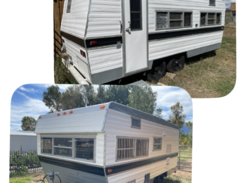
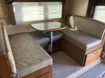
Okay, I’m super-excited about this!! Our Lance 1050s truck camper came with a remote that controlled the jacks and the slide. Since our remote failed on the last trip, I wanted to hardwire a switch. I couldn’t figure out how to wire it through our new Rieco-Titan board. Their diagram didn’t seem to match the system that I had. I came across a post on the Lance forums that was similar-but-not-quite what I was looking for. So here is what I did…
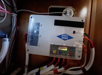
Our HappiJac slide-out has a little control board mounted near the motor. It looks like this:
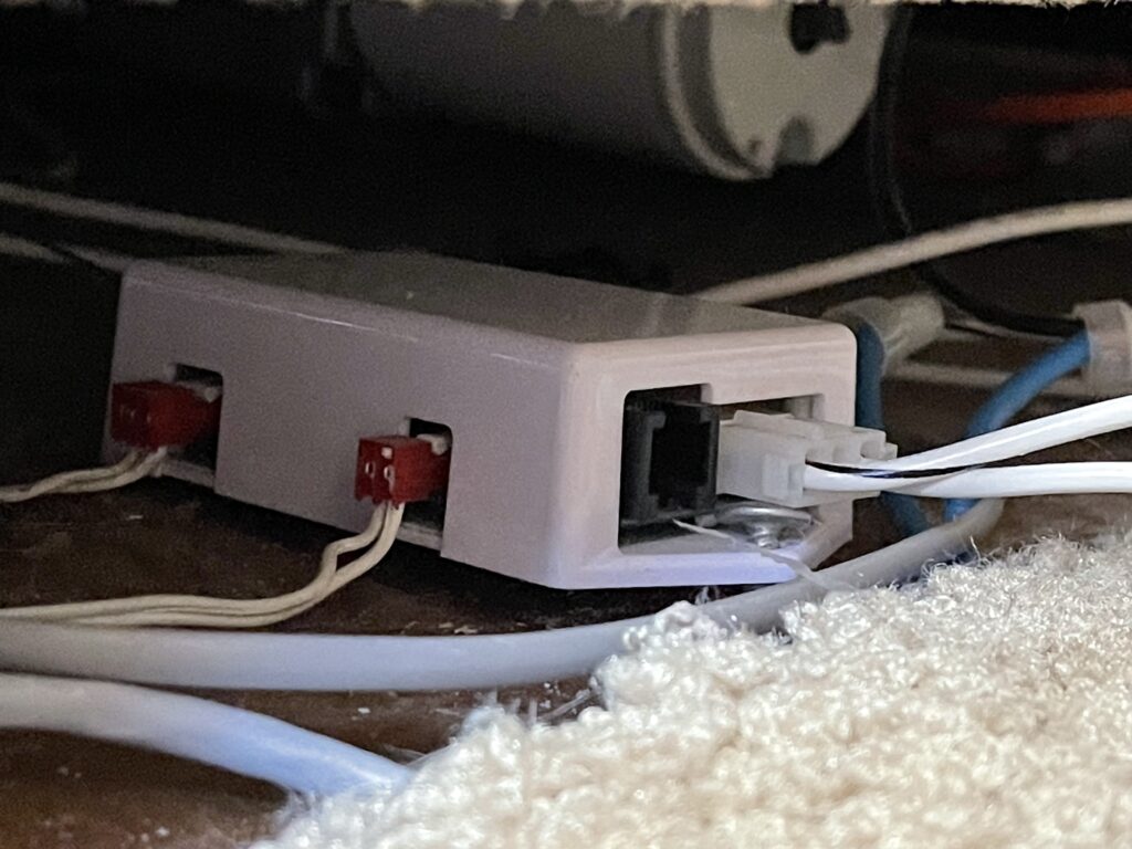
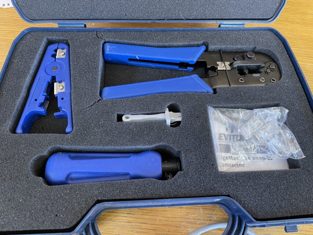
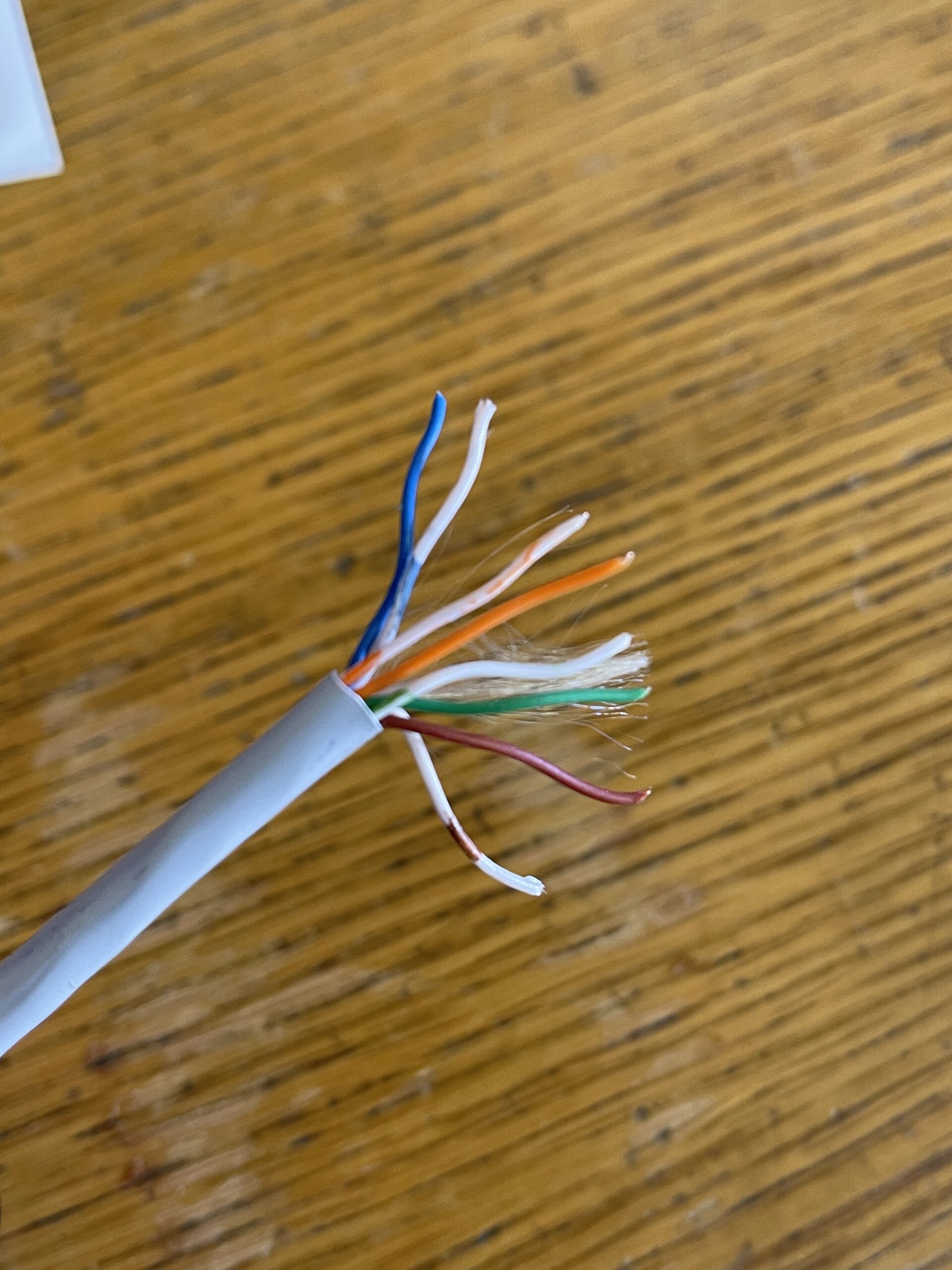
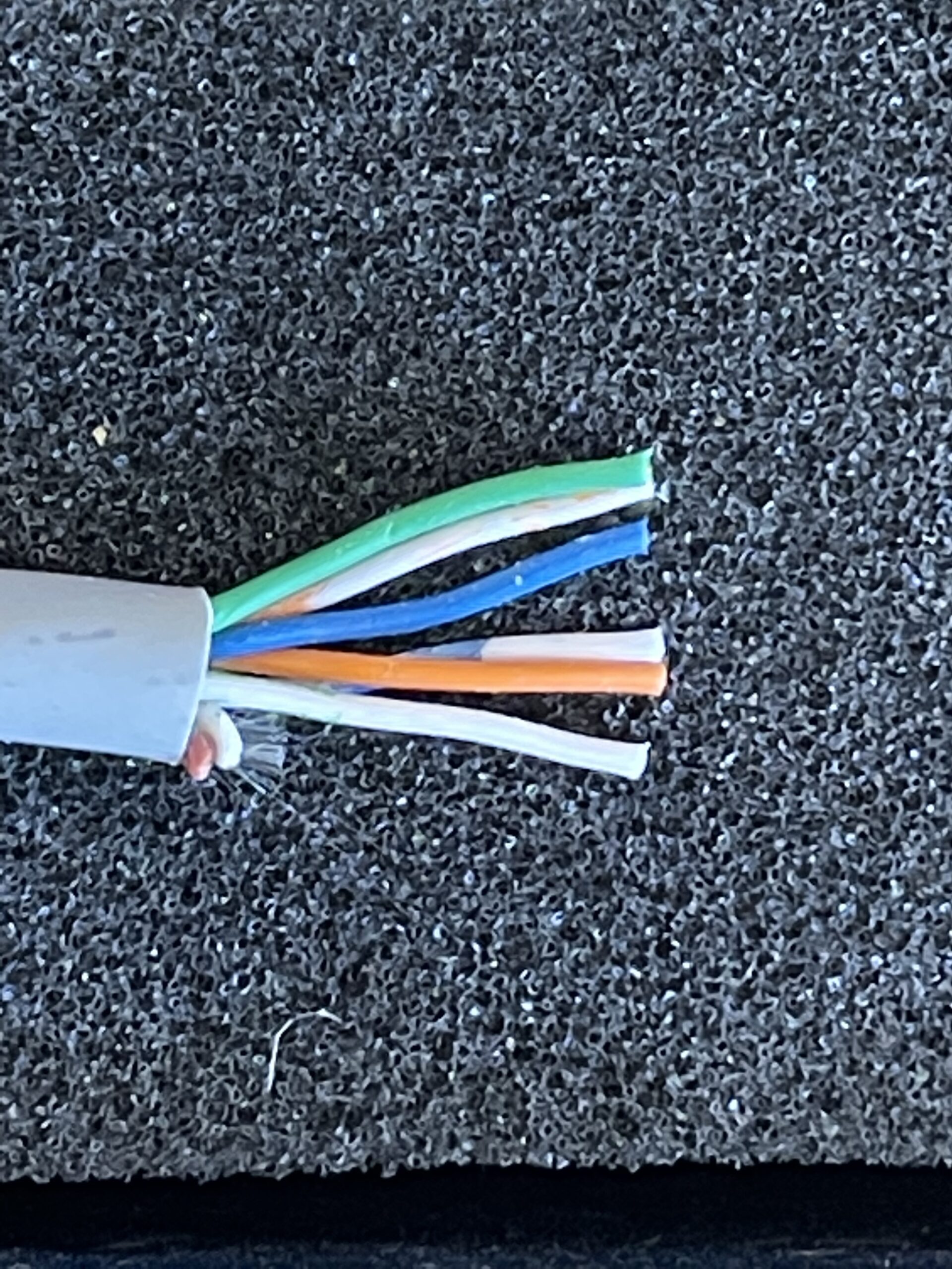
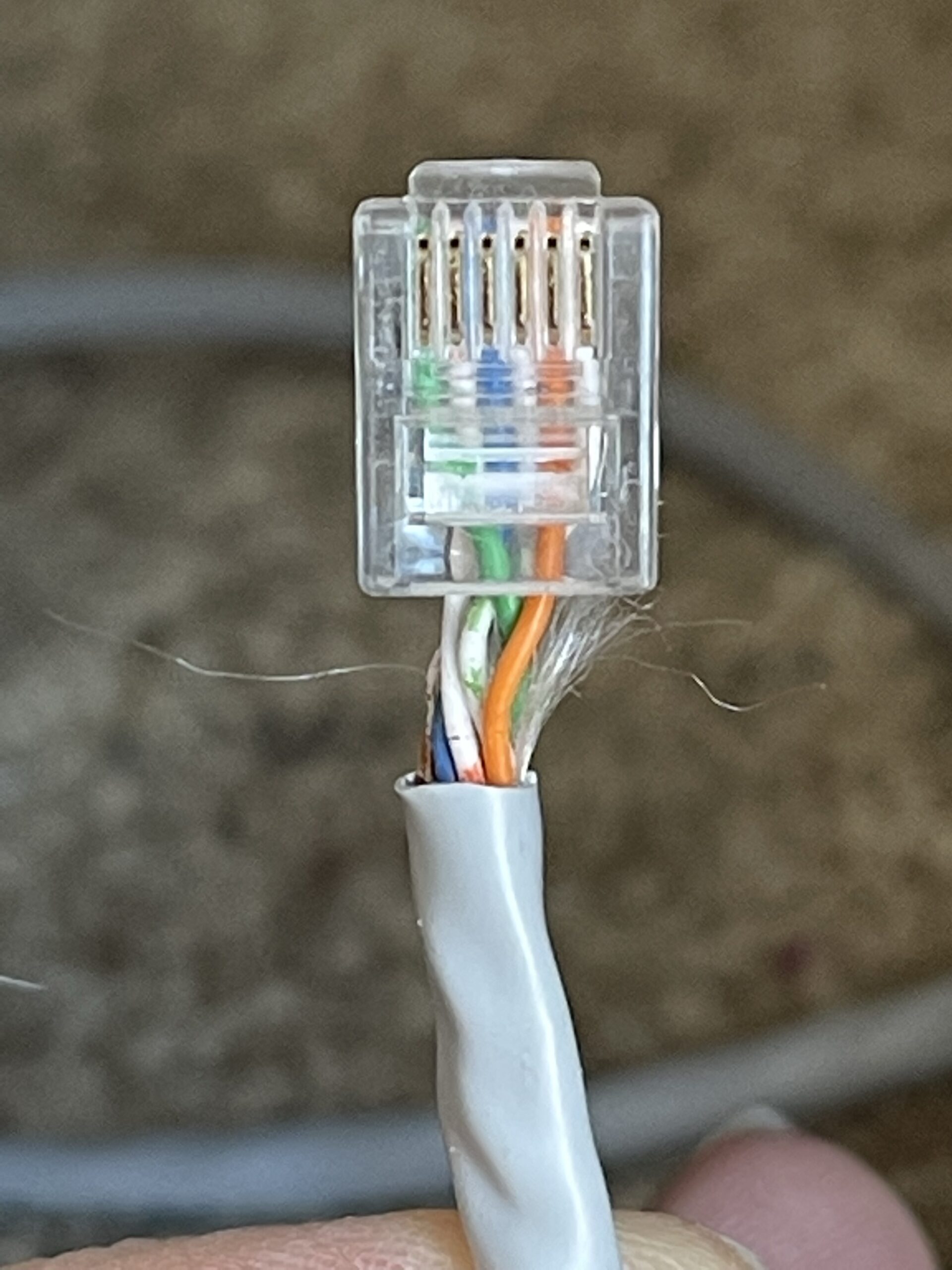
First, I unplugged the original cord from the jack in the control (as seen above). Then I used some Cat5 cable to make a new short data cable with RJ12 connectors, and made a little bit longer piece that I routed from the control board to the switch next to the door. I’ve had a data cable crimping set for a long time. I believe I bought it at Home Depot. You can find a similar one here: Network Tool Kit
Here are the tools that I used:
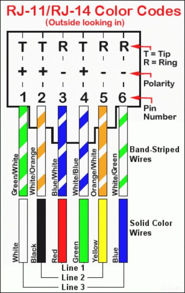
I ordered 6P6C RJ12 connectors (they have space for 6 wires) and a 6P6C 1 female to 2 female splitter. I found this diagram online and (kind of) followed it:

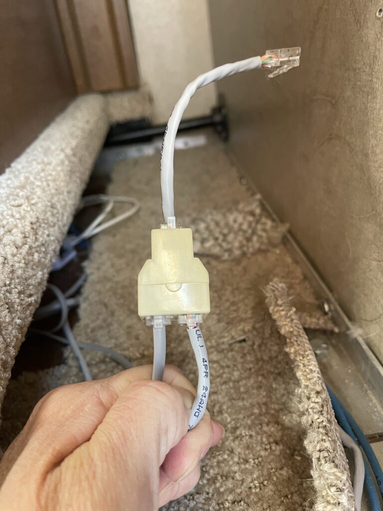
I added the short cable to the single side of the splitter and the original cable and one end of a newly-created cable to the side with two openings. That way, I can use either the remote OR the switch! Note that the photo on the right above is reversed from the diagram above. I changed it later, but it made no difference with the way the system worked.
I routed the new cable under the carpet along the blue cables that run to the manual switch, to the new rocker switch that I received from Rieco-Titan in their control board kit. It is a momentary reverse polarity rocker switch. When you stop pressing one side or the other, it goes back to the middle and stops.
Here is how mine is wired:
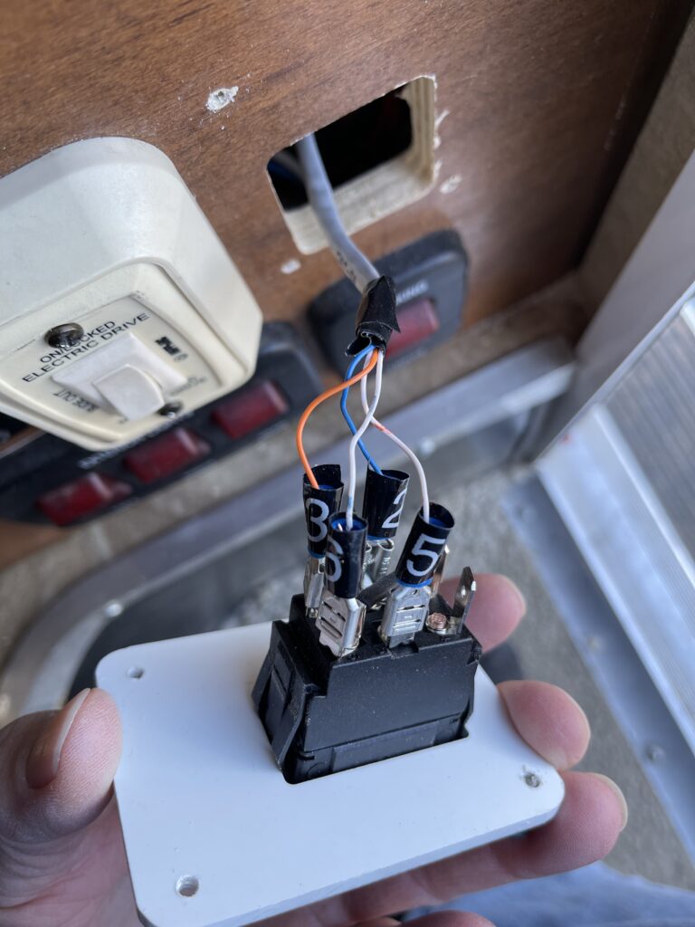
Strip the wire sheathing down to the copper and crimp female spade connectors to the wire. I had 14-16AWG connectors in my toolbox and didn’t want to go to the store for the smaller red ones, so I stripped the wires farther back and folded them over twice before I crimped them. On my switch, the white/blue wire is placed in the #6 position, blue wire placed in #2, orange on #3, and white/orange on #5. Snip off the green pair. This switch has jumpers between #1 and #6 and #3 and #4. When this particular switch is placed in the hole with the Rieco-Titan logo at the top, pushing UP on the switch extends the slide and pushing DOWN retracts it.
The LAST thing to do is plug the short wire on the splitter into the control box. The tab is on the floor side and the contacts are up. Make sure this is the last step, otherwise you may end up with the slide doing its own thing if you accidentally touch the wires together (don’t ask how I know). Then test the system. If your switch is backward, swap the white/blue and orange wires.
If you don’t already have Cat5 or Cat6 cable and a crimping tool around the house, I’m sure you can use premade 6P6C cables. If you use premade cables, just use the color chart above. I just happen to have a whole box of cable left from hardwiring a network and cameras at home.
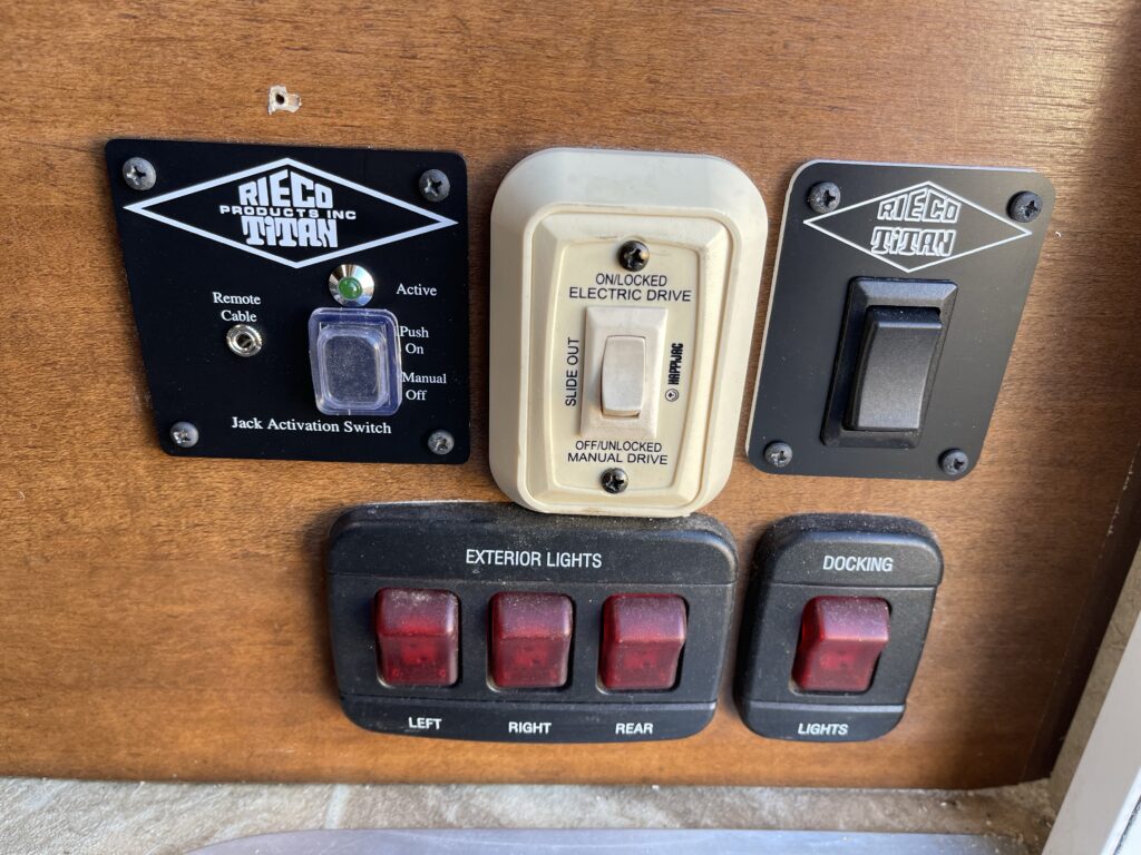
Here are all of the switches:
Let me know if this was helpful! I’m not an electrician so I probably can’t help if you don’t have the exact setup that I do, but I wanted to show that it IS possible!
Some links may be affiliate links. I may earn from qualifying purchases at no additional cost to you.
Minnie’s Mommy is a participant in the Amazon Services LLC Associates Program, an affiliate advertising program designed to provide a means for sites to earn advertising fees by advertising and linking to Amazon.com.